Sunday, April 7, 2013

Voltage Dividers

Objective: we need to determine the bus voltages so that anywhere between one to three loads can be applied to the voltage and still meet the voltage and current requirements.

first we calculate

Req,max= 1Kohm
Req,min=1/3Kohm

upper and lower voltage bounds are

max=6.25V
min=5.75V

plugging in equations


I bus,max=19.2mA
I bus,min=6.25mA


data collected from the three possible congigurations

Config Req Vbus Ibus Pload
1 load 1Ω 6.09V 6.1mA .04W
2 loads 1/2Ω 5.69V 11.4mA .065W
3 loads 1/3Ω 5.33V 16.1mA .086W

the actual percentage in load variation goes from 1.5% to 5.1% to 11%, the difference can be found from the imperfections in the tools used in the experiment, the variation of power given, the variation in the resistors and so on, everything factors in and creates problems for experiment.

if a fourth load was added, that would give us an Req of 1/4 a Vbus of about 5.0, an I bus of about 21mA and a Pload of about .11W

the new source parameters would have to be between 5.95-6.05.

in conclusion our tests went fairly well and our percentages almost made it within our requirements.

Intro to Biasing

Our objective is power and light up two separate LEDs that have different Voltage ratings and different current ratings. By doing Biasing we will attempt to establish correct voltages and currents across the LEDs so they will not burn out

we start by calculating the resistances needed to acquire our desired voltages.

R led1 176Ω R led2 350Ω

we then calculate the following

I R1 22.75mA I R2 20mA
V R1 4V V R2 7V
R1 176Ω R2 350Ω
P R1 .091W P R2 .14W

and after looking at the available resistors we decide to use

R1 220Ω R2 360Ω

we choose our resistors and acquire the following measurements

color code (List Colors) Nominal Value Measured Value Wattage
2200 220 213 1/8W
3600 360 352 1/8W
4700 470 459 1/8W

after building the ciruit


we obtain these values

Config I led1 V led1 I led2 V led2 I supply
1 10mA 5.9V 14mA 2.11V 24mA
2 10mA 5.9V X X 10mA
3 X X 14mA 2.11V 14mA

BONUS*


Both LEDs must be in this circuit for it to work properly because of increased current.

A. 8.3 hrs
B. 44%
C. 93%

Saturday, April 6, 2013

introduction to DC circuits

Our objective in this experiment was to determine the max cable resistance required, the max distance the battery and load can be separated with awg#30 cable, the distribution efficiency, and the time it takes for the battery to discharge

we determine the theoretical value for R(load) to be 1000Ω


Vload=11.01V
Ibatt=11.6mA
Rcabletot=73Ω


Time to discharge
.8Ahr/.0116A=68.97 hours

power to the load=.1309 W
power to the cable=.0098W

the efficiency is (.1309/(.1309+.0098))100=93%

we are not exceeding the power capability of the resistor box because we are well below .13w

the max distance of the wire is 73/.3451=105.77m


e. (optional)
the ohm per foot ratio in AWG#28 wire is 0.06490Ω
V=IR
5=(.020)R
R=250Ω
250/.06490=3,852 ft.

however we will probably not be getting ideal values, therefore done with a  voltage of .2
.2=(.020)R
R=10Ω
10/.06490=154 ft.

only being able to drop 12V I calculated R=1.2ohms dividing that by 150 ft. I get .024
therefore,
if the sub is approximately 150 ft. away then the minimum cable gauge would be #22

FreeMAT

experimenting with freemat

exercise 1
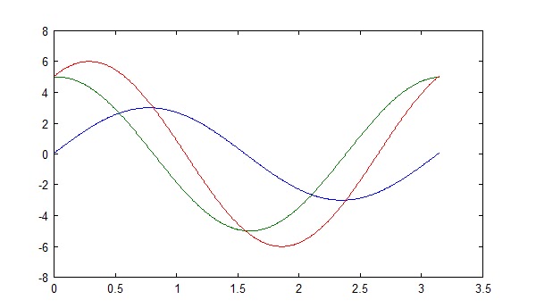
plotting sine and cosine functions


Assignment 1

-15=30i1-10i2
-7=-10i1+15i2

R =
  30 -10
 -10  15
--> V=[-15;-7]
V =
 -15
  -7
--> I=inv(R)*V
I =
   -0.8429
   -1.0286
I2-I1=I3
--> -1.0286-(-.8429)
ans =
   -0.1857

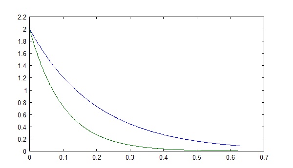
Assignment 1 circuit A vs B
1.
circuit A will have the lowest output sooner

2.
this time A has the higher output sooner

Assignment 2

yes the theoretical and the freemat outputs match, here is the picture
in conclusion I have decided that freemat is a very useful tool if you know what you are doing, and it appears to be simple enough to use that I will definitely use it in the future.