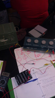
this is the circuit we are dealing with, as you can see we had to change the voltage sources to 12V sources because of availability. and the resistors used are as follows.
| Resistor | Nominal Value | Measured Value |
| R1 | 10k | 9.86k |
| Rf | 100k | 98.3k |
we predicted the value of the current leaving the op amp to be .1mA and then built the circuit.
| Vin Desired | Vin Actual | Vout Measured | Vrf Measured | Iop Calculated |
| 0.25 | 0.25 | -2.67 | 2.66 | .0266mA |
| 0.5 | 0.5 | -4.95 | 4.92 | .0492mA |
| 1 | 1 | -9.9 | 9.82 | .0982mA |
We measured
Icc=.933mA
Iee=-1.034mA
Therefore Iop=Icc+Iee
=.933-1.034
=-1.01mA
our power supplied by each of the 12V sources is
P=.0124W
P=.0112W
then we added a 1Kohm resistor
and measured
| Vin Desired | Vout Measured | Vrf Measured | Iop Calculated | Icc Measured | IEE Measured |
| 1V | -10 | 9.96 | .1mA | .73mA | -11.09mA |
KCL for the op amp continues to hold because the currents are at different values, which means it was divided through the circuit.
the new power supplied by each voltage source is
P=.133W
P=.0087W
Extra Credit
Rf=50Kohms
| Vin Desired | Vout Measured | Vrf Measured | Iop Calculated | Icc Measured | IEE Measured |
| 1V | -5.07V | 5.05V | 1.01mA | .932mA | -1.033mA |
these measurements do behave as expected because of the change in resistor it cuts the factor of 10 down to a factor of only 5. because the resistor is half as much as before.


